solid state relay/advantage and disadvantage of its and working principle.
solid state relay/advantage and disadvantage\ working principle?
solid state relay-
Advantage of solid state relay.
solid state relay can be divided into AC SSR and DC SSR according to applications. Now take AC solid state relay as example to explain SSR working principle. As Figure 1 show, it is a AC SSR working principle diagram and the parts ①~④ form its main body. As a whole, SSR only has 2 input terminals (A & B) and 2 output terminals (C & D). It is a four-terminal active device.
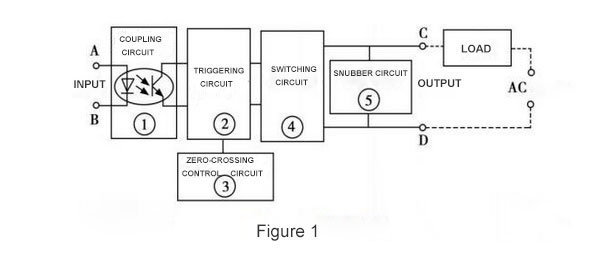
When operating, only place a certain control signal to A&B, able to control on-off state between C and D, and then achieve the switching function. The coupling circuit plays a role to provide a channel between input and output terminals for control signal input from A and B, but cut off the electrical connection between input and output to prevent the output from affecting the input. Components used in the coupling circuits are "optical couplers", which has good action sensitivity, high response speed, high level of input/output insulation (withstand voltage). The load at the input terminal is a light-emitting diode, which makes the SSR input very easy to match input signal level. In the use, it can be directly connected with the computer output interface, that is, it is controlled by the logic level of "1" and "0". Trigger circuit function is to generate the desired trigger signal to drive switching circuit work. However, without special control circuit, the switching circuit will produce RFI (Radio Frequency Interference) and pollute power grid as high harmonics or peaks, so zero-crossing control circuit is set for this purpose. Zero crossing means, SSR is on-state when placing the control signal and AC voltage crossing zero; after switching off control signal, SSR is not off-state until AC current is at the junction the positive half cycle and the negative half cycle (zero potential). This design prevents the interference of higher harmonics and the pollution of the power grid. Snubber circuit is designed to prevent the impact and interference to switching component Triac from the surges and spikes (voltage) from the power supply. Normally RC series snubber circuit or non-linear resistance (MOV) is used. Compared with AC SSR, DC SSR has no zero-crossing control circuit and snubber circuit inside, and large power transistor is usually used for the switching component. In addition, other work principles are the same.
solid state relay-
- It is non electro-mechanical device .which have no magnetic field ,spring etc
- it have no moving part and it is work on optical properties of solid state semiconductors to perform its input to output isolation and switching functions.
- Solid state relays can be designed to switch both AC or DC currents by using an SCR, TRIAC, or switching transistor(MOSFET) output instead of the usual mechanical normally-open (NO) contacts.
- it's long life to another relays.
Advantage of solid state relay.
- SSR have no internal mechanical elements and full-sealed perfusion in the structure. Therefore, SSR have advantages such as vibration resistance, corrosion resistance, long life and high reliability.
- which is create low noise because which have no moving part(so no chance of sparking ).
- Switching time is short(micro second), so SSR can be used in high frequency applications.
- Opto-electronic isolation is used between input circuits and outputs circuits, and insulation voltage up to 4 KV.
- Low power consumption.
- High load capacity.
- It is more expensive than electro-mechanical relay.
- May be destroyed on over load.
- Possibility of spurious switching due to voltage transients (due to much faster switching than mechanical relay)
- Isolated bias supply required for gate charge circuit
- Higher transient reverse recovery time (Trr) due to the presence of the body diode
- Tendency to fail "shorted" on their outputs, while electromechanical relay contacts tend to fail "open".
solid state relay can be divided into AC SSR and DC SSR according to applications. Now take AC solid state relay as example to explain SSR working principle. As Figure 1 show, it is a AC SSR working principle diagram and the parts ①~④ form its main body. As a whole, SSR only has 2 input terminals (A & B) and 2 output terminals (C & D). It is a four-terminal active device.
When operating, only place a certain control signal to A&B, able to control on-off state between C and D, and then achieve the switching function. The coupling circuit plays a role to provide a channel between input and output terminals for control signal input from A and B, but cut off the electrical connection between input and output to prevent the output from affecting the input. Components used in the coupling circuits are "optical couplers", which has good action sensitivity, high response speed, high level of input/output insulation (withstand voltage). The load at the input terminal is a light-emitting diode, which makes the SSR input very easy to match input signal level. In the use, it can be directly connected with the computer output interface, that is, it is controlled by the logic level of "1" and "0". Trigger circuit function is to generate the desired trigger signal to drive switching circuit work. However, without special control circuit, the switching circuit will produce RFI (Radio Frequency Interference) and pollute power grid as high harmonics or peaks, so zero-crossing control circuit is set for this purpose. Zero crossing means, SSR is on-state when placing the control signal and AC voltage crossing zero; after switching off control signal, SSR is not off-state until AC current is at the junction the positive half cycle and the negative half cycle (zero potential). This design prevents the interference of higher harmonics and the pollution of the power grid. Snubber circuit is designed to prevent the impact and interference to switching component Triac from the surges and spikes (voltage) from the power supply. Normally RC series snubber circuit or non-linear resistance (MOV) is used. Compared with AC SSR, DC SSR has no zero-crossing control circuit and snubber circuit inside, and large power transistor is usually used for the switching component. In addition, other work principles are the same.


Comments
Post a Comment